Services
Portable Appliance Testing Portable Appliance Testing Portable Appliance Testing
A Portable Appliance is any item of electrical equipment capable of being plugged into an electrical socket outlet.
Examples
- Fridges
- Kettles
- Toasters
- Laptops
- PC’s
- Printers
Portable Appliance Testing (PAT) is a test that involves a visual inspection on each item of equipment within premises. Each item of equipment is then connected to a test meter to confirm the integrity of the internal wiring of the equipment. This inspection is to be carried out on an annual basis.
Portable Appliance Testing was devised in the interest of public safety and it is now a requirement in the eyes of government and insurance companies alike. It is necessary for employers to undertake this low-cost procedure annually for everybody’s safety (including the public) and for peace of mind.
S.I. No. 299/2007 – Safety, Health and Welfare at Work (General Application) Regulations 2007
Portable equipment.
81. (1) An employer shall ensure that—
(a) a circuit supplying portable equipment or a socket outlet intended to supply portable equipment, including any circuit supplied by an electrical generator, and in which is used alternating current at a voltage—
(i) exceeding 125 volts, and
(ii) not exceeding 1,000 volts,
is protected by one or more residual current devices having a tripping current not exceeding 30 milliamperes operating within such period of time so as to provide the necessary protection to prevent danger to any person coming into direct or indirect contact with any live part of the circuit,
(b) portable equipment is maintained in a manner fit for safe use, and
(c) portable equipment which is—
(i) exposed to conditions causing deterioration liable to result in danger, and
(ii) supplied at a voltage exceeding 125 volts alternating current,
is—
(I) visually checked by the user before use, and
(II) periodically inspected by a competent person, appropriate to the nature location and use of the equipment.
(2) An employer shall ensure, where appropriate, that a competent person—
(a) tests any portable equipment described in paragraphs (1)(c)(i) and (ii), and
(b) certifies whether or not the portable equipment (including any cables and plugs was, on the day of the test, as far as could reasonably be ascertained, safe and without risk to persons coming into direct or indirect contact with any live part of the equipment.
The law simply requires an employer to ensure that their electrical equipment is maintained in order to prevent danger. It does not say how this should be done or how often. Employers should take a risk-based approach, considering the type of equipment and what it is being used for. If it is used regularly and moved a lot e.g. a floor cleaner or a kettle, testing (along with visual checks) can be an important part of an effective maintenance regime giving employers confidence that they are doing what is necessary to help them meet their legal duties. ATS provides guidance on how to maintain equipment including the use of PAT.
The frequency of testing depends on many factors such as appliance use, the area of use, user, age, and class of appliance. It is recommended to carry out Portable Appliance Testing annually. It is recommended to do this every six months on Construction Sites.
Periodic Electrical Inspection Periodic Electrical Inspection Periodic Electrical Inspection
A Periodic Electrical Inspection otherwise known as Fixed Wire Testing is an inspection and associated testing to check whether an electrical installation is in a satisfactory condition for continued service. On completion of the necessary inspection and testing, an Electrical Installation Condition Report will be issued detailing any observed damage, deterioration, defects, dangerous conditions and any non-compliance with the present-day safety standard which might give rise to danger.
Visual Inspection
A regular visual inspection should be carried out on all electrical installations. A visual inspection should look for:
Breakages
- Wear & deterioration
- Signs of overheating
- Missing parts (covers, screws)
- Switchgear accessibility
- Residual current devices test
- Time Intervals between Periodic Inspections
- The time between periodic inspection and testing of installations should be based on a risk assessment with the intervals dependent on a number of parameters such as the:
- age of the installation,
- quality of the installation,
- environmental circumstances,
- type of persons using the installation,
- amount of supervision of the person responsible for the installation,
- guidance of the manufacturer,
- possibility of damage to the equipment.
Types of Inspection and Testing to be done during formal Inspection & Testing.
The following non-exhaustive list indicates the types of inspection and tests that are necessary
to complete the periodic inspection and testing of an installation.
A general appraisal of the installation by a competent person to assess the physical condition
of the installation and its suitability for its environment.
Continuity of the protective conductors and of the main supplementary equipotential
bonding.
Continuity of conductors in ring final circuits.
Resistance of protective conductor.
Insulation resistance of the electrical installation.
Polarity.
Fault Loop Impedance test.
Verification of Operation of RCDs including the tripping times of all RCDs.
These tests are set out in more detail in chapter 62 of the ETCI National Rules for Electrical Installations.
It could also include other tests depending on the nature of the installation.
These additional tests might include
thermal imaging,
ultrasound scans, and
other tests as dictated by the installation.
The maintenance of equipment, particularly safety devices, according to manufacturers’ instructions,
Legislation
The requirement for the periodic inspection testing and reporting is set out in Regulation 89 of the 2007 Safety Health and Welfare at Work (General Application) Regulations (S.I. No 299 of 2007) as amended by the Safety, Health and Welfare at Work (General Application)(Amendment) Regulations 2007 (S.I. No. 732 of 2007) ), which states that
“ an employer shall ensure that— ………………………………………….. (b) an existing electrical installation is tested by a competent person in an appropriate manner– (i) from time to time where required having regard to the nature, location and use of the installation,” and that Revision 1 (30-Oct-2014) Page 2 of 7 “(d) all defects found during the testing and inspection of an electrical installation are rectified promptly so as to prevent danger. …………………………. and a report of the test is completed by the competent person carrying out the test,”
| Type Of Workplace | Suggested Period Between Visual Check | Suggested Period Be tween Inspection & Testing |
| Commercial | 1 Year | 5 Years |
| Educational establishments | 1 Year | 5 Years |
| Hospitals | 1 Year | 5 Years |
| Industrial | 1 Year | 3 Years |
| Residential accommodation | 1 Year | 5 Years |
| Offices | 1 Year | 5 Years |
| Shops | 1 Year | 5 Years |
| Laboratories | 1 Year | 5 Years |
| Agricultural / Horticultural | 1 Year | 3 Years |
| Cinemas | 1 Year | 3 Years |
| Leisure complexes(excluding swimming pools) | 1 Year | 3 Years |
| Restaurants / Hotels | 1 Year | 5 Years |
| Theatres | 1 Year | 3 Years |
| Public houses / Bars | 1 Year | 5 Years |
| Laundrettes | 1 Year | 1 Year |
| Petrol stations | 1 Year | 3 Years |
| Marinas | 4 Months | 1 Year |
| Construction sites | 3 Months | 6 Months |
Thermal Imaging Thermal Imaging Thermal Imaging
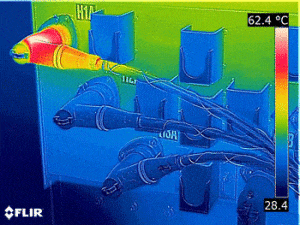
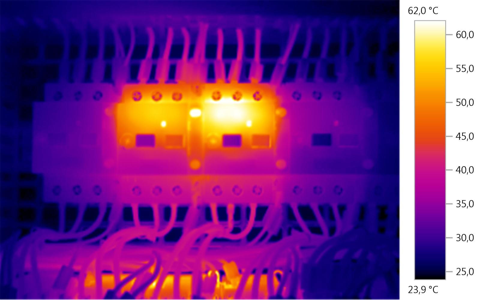
An electrical thermal imaging survey incorporates the use of an infrared camera to highlight areas of potential problems and failures of electrical devices, such as fuse boards, terminals, electric motors, transformers and electronic devices.
Reduction in breakdown maintenance costs. Increased availability of insurance companies willing to provide cover. Reduction in insurance premiums. Reduction in risk mitigation contingency budgets. It is extremely fast and accurate.
Surveys of electrical systems can expose faults such as poor connections, overloaded circuits, and imbalanced load. Alternating current often loosens connections which in turn causes breakdowns & possible electrical fires. If trouble already hit or you just want to prevent it, call ATS for advice.
Thermal Imaging Testing (Thermography) detects potential problems and failures of electrical devices, such as fuse boards, terminals, electric motors, transformers and electronic devices. The structural part of the electrical appliance radiates heat which can be detected using our Thermal Image cameras. Regular imaging inspections will identify problems before trouble hits.
Electrical Thermal Imaging Survey
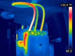
Thermal Image inspection and monitoring of electrical installations identify faulty electrical components that begin to deteriorate as soon as they are installed. Whatever the loading of a circuit, vibration, fatigue and age cause the loosening of electrical connections, while environmental conditions can hasten their corroding. Briefly stated all electrical connections will, over time, follow a path towards failure. If not found and repaired, then these failing connections will lead to faults. Fortunately a loose or corroded connection increases resistance at the connection and this increased resistance causes an increase in heat. Electrical Thermal Imaging will detect this developing fault before it fails.
Detecting and correcting failing connections before a fault occurs will prevent fires & unplanned loss of electrical supply, which in turn will prevent loss of earnings.
Thermal Imaging provides a quick and efficient method of finding electrical and mechanical components that are operating above their correct temperature.
Surveys are carried out under normal working conditions, which therefore involves minimal interference to your business.
We can perform thermal imaging on your electrical distribution boards and switch gear.
The thermal camera will detect heat known as hot spots and show early warning signs of electrical components that are at risk of failure.
A completed detailed report showing thermal image photographs and containing accurate temperature readings.
We will also give advice and recommendations on any repairs as required.
Energy Auditing & Load Studies Energy Auditing & Load Studies Energy Auditing & Load Studies
Energy logging is now within your reach—discover where you’re wasting energy, optimize your facility’s energy use and reduce your bill.
Discover when and where energy in your facility is being consumed; from the service entrance to individual circuits. Call us for advice.
Discover how much energy individual pieces of equipment are consuming when they are operating at minimum and maximum capacity. Check the capacity of circuits prior to adding additional loads.
Load studies: Discover how much energy individual pieces of equipment are consuming when they are operating at a minimum and maximum capacity. Check the capacity of circuits prior to adding additional loads (various standards exist for this process; in the US the NEC 220-87 is the recommended standard). Load studies can also identify situations where you may be exceeding the allowable load on the circuit or when an agreed peak demand applies from the utility. For convenience, some load studies simply measure current which makes the installation of the measuring equipment quick and easy. It is often recommended that load surveys be performed for 30 days so that all typical load conditions are encountered during the test.
Energy assessments: quantify energy consumption before, and after improvements, to justify energy saving devices.
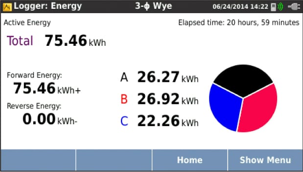
Power and energy logging: When a piece of equipment is operated it instantaneously consumes a specific amount of power in watts (W) or kilowatts (kW). This power is accumulated over the operating time and expressed as energy consumed in kilowatt hours (kWh). Energy is what your electric utility charges for; there will be a standard charge from the utility per kilowatt hour. Utilities may have other additional charges, such as peak demand, which is the maximum power demand over a defined period of time, often 15 or 30 minutes.
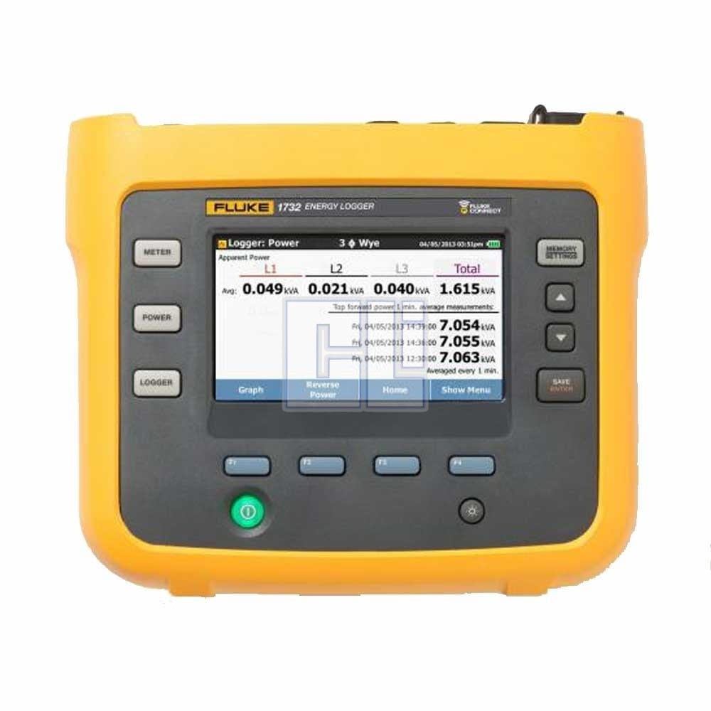
There may also be power factor charges, which are based on the effects of the inductive or capacitive loads in the facility. Optimizing peak demand and power factor often result in lower monthly electricity bills. The 1733 and Fluke 1734 Three Phase Electrical Energy loggers have the capability to measure and characterize these effects enabling you to analyze the results and save money.
Log the most common parameters
Designed to measure the most critical three-phase power parameters, the 1732 and 1734 can simultaneously log RMS voltage, RMS current, voltage, voltage and current THD, active power, reactive power, power factor, active energy, reactive energy, and more. With enough memory for more than a year of data logging, the 1732 and 1734 can discover which loads are can be optimized to enable you to reduce your energy bill.
Simple setup means all available measured parameters are automatically selected during logging so you can be sure you have the data you need, even before you know you need it.
Tools
Fluke 1738 Three-Phase Electrical Energy Loggers
We use the new Fluke 1738, now with Fluke Connect capabilities.
KEY MEASUREMENTS
Automatically capture and log voltage, current, power, power factor, energy, and associated values
FLUKE CONNECT® COMPATIBLE*
View data locally on the instrument, via Fluke Connect mobile app and desktop software or through your facilities’
WiFi infrastructure.
CONVENIENT INSTRUMENT POWERING
Power instrument directly from the measured circuit
HIGHEST SAFETY RATING IN THE INDUSTRY
600 V CAT IV/1000 V CAT III rated for use at the service entrance and downstream.

